

This program is designed to work in conjunction with the SkyAlert weather system module and will not function correctly with other weather data generating instruments.
Program Installation:

Follow the on-

After the device drivers installation has completed, continue by clicking the “Exit” button on the SkyAlert Install program window. Click “Install” on the next window to complete the installation.

SkyAlert Installation
Mounting the SkyAlert Sensor Module:
The Sensor Module comes with a mounting bracket. Mount the bracket to the side of
the Sensor Module, as shown below,with the (2) #10 screws provided. After mounting
the bracket, it may then be clamped to any vertical mast ( ~1" to 1-


Specific Imaging Automation Software Instructions:
ACP: Click on “ACP” from the main toolbar at the top of the of the window and select “Preferences”. Click on the tab labeled “Weather”. In the Weather server object ID field, type in ACP.BoltwoodFile Click on the Setup Weather Server button and navigate to the location of the weather data file created by SkyAlert. You may need to change the extension setting in the file browser from .log to (All Files) in order to locate the weather data file. From the main screen menu, select the toolbar drop down item labeled “Weather” and then click “Connect”. After a few seconds, the “WEA” icon should light up indicating weather status.
CCD AutoPilot: On the “Setup” page, select “Cloud Sensor” from the “Weather” drop down item box. Click on the “Settings” option from the main menu on the left and then select the “Control Settings” tab at the top of the window. In the “Weather Sensor” group box, click the file path button and navigate to the file location of the weather data file being generated by SkyAlert (weatherdata.txt). To confirm connection, click “Link to Software” on the Setup page. After connecting to the software, click on the “Run” menu item. The current weather conditions should be displayed in the list box on the upper left area of the window.
CCD Commander: Click on the “Setup” menu item on the toolbar at the top of the program window, then select the Control/Device tab. From the Weather Monitor drop down, select “Boltwood/Clarity II Remote”. Click on the “...” Button adjacent to the weather monitor path text box and navigate to the location of the SkyAlert weather data file. Now, click on the “Weather Monitor” tab and set the weather action check boxes as desired. From the main menu, click the “Actions” drop down and ensure that the Weather Monitor Action is set to “Enabled”.
Additional Features:
SkyAlert features many built-
Weather Data File:
The weather data file generated by SkyAlert conforms to the standard one-
SkyAlert User’s Guide
Graph 1-
Specify the title name of each graph by typing a name in the “Graph title” field.
Graph 1 is set to chart the Ambient Temperature and the Sky Temperature (the chart will fill in the area between the two graph lines with a color coded zone indicating the condition of the sky. (Clear, Cloudy or Very Cloudy).
Graphs 2-
You can specify which weather conditions will be charted on each of the four custom graphs by checking the weather criteria check boxes and include as many plots as desired on each graph. In addition, an external temperature sensor can be monitored and graphed by ticking an “Ext. Sensor” check box. This function is only available when running SkyAlert with SkyAlert Remote connected to an external Phidget 1051_2 sensor. Contact support@interactiveastronomy.com for details.
The minimum and maximum values of the Y-
Type a name for the Y-
Clicking the “Graph” check box on the main menu will show the current graphs. If
the graph page is hidden by un-
Program Settings:
In order for the program to function, it will need to collect data from the SkyAlert weather module. Two different methods of data collection are provided for this purpose, “Local” connection or “Remote” connection. Using the “Local” connection means the weather module is connected directly to a USB port on the computer running the program. For “Remote” connections, the weather module is connected to a networked computer running the SkyAlert Remote program and the data is retrieved over a network connection. This method can be useful for connecting multiple computers to a single weather system module or as a failsafe backup in case a module malfunctions. Either way, the computer connected to the weather module will need to have the hardware drivers installed and will need to be running either the SkyAlert program or the SkyAlert Remote program.
Local Connection:
Connect the weather module to a free USB port on the computer, select the “Local” radio button, select the appropriate com port from the drop down Com Port selection menu and click the “Connect” button. If you are uncertain which port the weather module is connected to, continue selecting com ports until the label adjacent to the Connect button indicates that the device is connected. Note: As long as there are no hardware changes, this only needs to be done the first time the program is run. On subsequent sessions, the program will automatically connect to the module when it is launched.
Remote Connection:
Before continuing, connect the SkyAlert module to the remote computer and launch the SkyAlert Remote program. Launch SkyAlert on the local computer, open the Settings page and click “Remote” radio button. A navigation button adjacent to it will appear. Click on the button and navigate to the location of the data file generated by the SkyAlert Remote program. (The default name for this file is “remotedata.txt”). Note: As long as there are no file location/name changes, this only needs to be done once. On subsequent sessions, the program will automatically connect to the remote file.
Enable Backup SkyAlert:
Check this box if an auxiliary remote weather module is connected to another computer on the network.
Com Port:
Use this drop down to select the com port that the SkyAlert weather module is connected to then click the ‘Connect’ button to establish the connection.
Top Most Window:
Ticking the “Top Most Window” checkbox will keep the main menu as the top-
Weather Data File Settings:
When the “Create Weather File” checkbox is ticked, the program will generate and save a standard one line weather data file (i.e. Boltwood II) to a specified file location. Click on the adjacent “Save to” button to select a name and file path to save the file to.
The “Cloudy Offset” setting can be adjusted to determine when the sky is cloudy.
This number is the difference of the measured sky temperature subtracted from the
measured ambient temperature and will determine when the weather data file reports
a cloudy condition. You may need to adjust this setting to suit your particular climate
or conditions. The default value is -
Safe/Unsafe Limits:
The “Wind Limit” setting determines the maximum allowable wind speed before an unsafe wind speed alert is reported in the weather data file.
The “Humidity” setting can be set to the desired maximum humidity level before an alert is set.
The “Temperature” setting threshold can be adjusted to set an alert if the ambient temperature drops below the set value.
Checking the “Dew Point” check box will set an alert if the dew point is reached.
Checking the “Daylight” check box will set an alert if daylight is detected.
Checking the “Error/Malfunction” check box will set an alert if any data or hardware malfunction should occur. (It is recommended that this check box remains checked unless you have a specific reason to leave it unchecked)
Graph Settings:
Set the name of the graphs page by typing a name in the “Graph Page Title” text field. This is the title that will appear at the top of the Graph window.
The “Graph Timeline” setting determines the length of the timeline the graph will show. This can be set from one to three days. After the timeline setting has been reached, the oldest graph data will be overwritten.
Ticking the “Top Most Window” checkbox will keep the graph page top-
Tick the “Save Graph Image to File” checkbox if you would like a snapshot of the graph saved as an image file. This is necessary if you plan on uploading an image of the graph to the web. Click on the adjacent “Save to” button to set a name and file path to save the image to. Image files can be saved as .png or .jpg. A new image will be generated each time the weather data is updated. If the ftp client is connected, the current graph image will be uploaded to the host.
The settings instructions are sorted by groups starting at the top left of the settings page.
02/18/2017
After finishing the installation, connect the SkyAlert module USB cable to a free USB port on the computer.
Note: Some USB 3.0 chipsets may not function correctly with SkyAlert. If you experience difficulties, connect SkyAlert to a USB 2.0 port. (USB 3.0 ports can be usually be identified by a blue connector.)

Proceed by selecting the "Tools" selection from the drop down menu and clicking on the "Settings" option. This will bring up the "Settings" page.
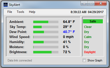
Program Operation:
When the program is started, the main dialog will appear displaying time, date, current weather conditions and a few options.
Calibrate sensors:
Moisture Sensor:
The values for the moisture sensor can be adjusted to fine tune the thresholds for dry, damp and rain if needed. The measured value currently generated by the weather module is displayed below the adjustment setting to facilitate the adjustment. The default values are Dry=990 and Rain=970.
Wind Sensor:
The zero wind speed setting can be adjusted to fine tune the wind speed setting. Adjust the setting so that the wind speed is slightly above zero (i.e. .001) when the wind sensor is completely shielded from any breeze or turbulence. The default value is .200. Note: although the value seems small, the zero wind volts setting has a major impact on the indicated wind speed.
IR Sensor:
Normally, the calibration of the IR sensor can be left at the default setting of zero. Adjustments can be made if necessary.
Light Sensor:
The light sensor can be calibrated to match your particular environment and installation position. The default values are Day=500 and Dark=250.
Ambient Sensor:
The Ambient temperature sensor can be calibrated if needed. The default setting is zero.
Humidity Sensor:
Default is zero.
Barometric Sensor: (Where available)
Adjust the pressure value to match a current known value in your area (local airport web site, etc.)
Cloudy/Very Cloudy Offset:
This adjustment dictates the difference between a Cloudy condition and a Very Cloudy condition. You may have to experiment with this setting to get optimum results.
Solar Offset:
The solar offset makes an adjustment to the ambient temperature based on whether or not direct sunlight is shining on the weather module.
The Offset value should be adjusted to the amount of temperature increase that is noted when the sun is shining on the weather module.
You can set the relative time of day for the algorithm to begin by setting the ‘Start’ value to how many minutes after sunrise that the sun will begin
to strike the module. Conversely, set the ‘Stop’ value to the approximate time that the sun will cease warm up the weather module.


SkyAlert has several feature and options which are available from selecting menus from the drop down menu bar of the Main dialog.
From the “File” menu drop down, a daily weather file is available. This file shows weather conditions recorded every ten minutes for the last 24 hours. Also available from the file drop down is a shortcut to the folder location of archived weather logs. Weather logs are kept up to one year before they are deleted.
The “Tools” menu drop down contains several selections which are outlined in the pages below.
Ftp Settings:
Weather graph images can be optionally uploaded to a web host for web page display. To connect to a web host, enter hosting credentials in the Hostname, Username and Password fields and then click the “Connect/Disconnect” button. If a connection is successfully established, in a few moments the list box to the right will populate with the names of the files currently on the server.
When the ftp browser list is populated, the contents of the server will appear with
folders at the top followed by files listed in alphabetic order. To open any of the
folders, double click on the <Folder> title. With the cursor positioned within the
file list, right click for more navigation options. After a location has been determined
to upload the file to, type in a name for the file in the “Filename” field. (The
default filename is weathergraph). This will be the filename used in your html code
to display the image on a web site. It is not necessary to add a filename extension
as this will be automatically determined by the file image type. The upload interval
can be set by adjusting the Upload Interval control to the desired interval time.
Click on the “Save” button to save the settings and click the “Close” button to continue.
The log-
In addition to uploading the image file, SkyAlert will upload a copy of the one line weather data file in the same folder. This can be be useful for sharing weather data to multiple locations that cannot otherwise access the file.
Note: The ftp browser does not support double-

Main Menu:
After you have completed making the selections on the ‘Program Settings’ page, click the “Done” button in the lower right hand side of the page to continue.

Options are available to set formats and scales to the desired scale setting. Use the radio buttons to make the desired changes and click the ‘Done’ button to continue.
Scale Settings:


